
BMW E39-RPi Homebrew Navigation System
Motivation
I wanted to:
- have the steering wheel buttons change the track on a bluetooth paired phone
- have modern map data on the screen (the latest MK4 DVDs go up to 2015)
- learn Jetpack Compose
- simplify the original phase of the project, reduce the dependency on the European TV Tuner module for the backup camera.
- Make some useful apps for the device so I could be less dependent on my smartphone when I’m out of the house.
Some day I’d like to:
- Finish the Calendar app to subscribe to CalDAV feeds in the car
- Run the Jetpack Compose HMI on a jailbroken Surface RT mounted to the side of my fridge.
Timeline
I started working on this project in September 2020.
The initial Kotlin/Jetpack Compose work was done in early 2021. By spring 2021 I had the UI responding to knob turn events. In June 2021, I wrote the map view. By August 2021, I finished the keyboard. Much of the Jetpack Compose UI was wrapped up by the end of 2021.
In February 2022, I focused on getting the RPi to output the right kind of video to the BMW display. I spent over 100 hours in February 2022 getting the VGA timing just right.
At the end of 2022 I expanded the scope of the project to add a Pi Pico to the design to learn some C++ and to provide a reliable way to turn the device on/off in the car.
By the end of 2023, I had the Pico firmware mostly done.
In 2023-2024 I designed a bunch of test boards and the main-board. By mid-2024 I had finished up a working prototype of the mainboard.
In November 2024 - January 2025, I wrote a Matrix Chat Client for the car.
In Spring-Fall 2025, I documented the project.
Architecture
The e39-rpi project is made of several components.
It is a Rasberry Pi embedded Linux device running a Jetpack Compose for Desktop GUI on an X-server. The RPi is attached via GPIO, Power, and USB to a HAT that I designed.
It is designed to be wired into the e39 and make use of the existing displays and buttons.
Car Hardware
The diagram below shows how the e39-rpi board and some of its components work together.

Software Architecture
High level
The Raspberry Pi runs an embedded linux distro that runs my HMI.
The Pi Pico runs a bare-metal firmware that I wrote called “Linster OS for Automotive”
Jetpack Compose HMI
The Jetpack Compose HMI is a desktop Linux app I wrote that runs on my development laptop as well as the RPi Raspbian image.
It interfaces with the hardware by:
- BlueZ-DBus to have a bluetooth pairing wizard implemented in the HMI
- PipeWire to forward BT audio to the speakers. (Laptop Speakers on the dev machine, Audio out on the RPi to BMW Radio Aux in)
- Serial port for incoming IBUS messages.
The HMI uses the Compose MPP WindowManager hints to maximize itself without a titlebar on the RPI. On the dev laptop, it is convenient to work with alongside IntelliJ.
The HMI Window has screens managed by the navigator. When I started in 2021, there weren’t that many off-the-shelf screen navigation libraries to choose from, so I wrote my own.
I made my own widget design system that allows all the Compose UI to be controlled by the rotary knob on the BMW display.
Linster OS For Automotive (Pi Pico firmware)
The Raspberry Pi Pico firmware acts as a hardware controller for the Raspberry Pi in the car.
Functions:
- Relay IBUS messages from the car to the RPi and vise-versa
- listen to IBUS Ignition Key events and turn on the power supply for the RPi.
- send graceful shutdown request messages to the RPi when the ignition key is turned off, before cutting the power to the RPi so that the 12v battery isn’t drained.
- listen to telephone button long-press events so that the user can reboot the RPi when the HMI gets stuck
- listen to telephone button press events to change the screen’s video input source between the RPi and the factory nav system.
- not relay knob turn/press events to the RPi when the RPi isn’t the selected video source, so that navigating in the factory menu isn’t manipulating the menus in the RPi.
Pico-Pi Private Message Protocol
The Pi and Pico send each other special messages over the same IBUS link, allowing the Pi to control the PICO hardware directly and set configured behaviour. The Pico can send messages to the Pi as well, to respond to configuration queries, warn the Pi of impending shutdowns, and send log messages.
Raspbian Firmware (RPi)
This is a prototype setup that needs some initial setup work to setup the HMI environment.
System Builder
Matthias Stone helped me out with this prototype image builder in late 2021.
What it does:
- Gets a Raspbian-Lite image
- Sidesteps the Pi-Gen script machinery
- Uses an ubuntu docker image to create an
e39-depspackage. This package has dependencies on all the things “a system should have”. A post-install script on the package does some extra setup work. - The
e39-depspackage and some other stuff are loaded onto the Raspbian image by mounting one partition of it as a loopback device. - There’s a
configure.shscript that does some more setup work - Some wifi information, username and password config, is setup beforehand so that on first boot the PI can work.
- The
/boot/config.txtwith the right vga timing info is coped to/bootso that the RPI’s display is visible on the e39-rpi.
Development environment
The e39-Rpi HMI is very easy to develop. On the dev laptop, you can iterate quickly. When you want to deploy to the RPI, run piDeploy.sh which will:
- Build an armhf version of the HMI
- Upload it to the RPi
- Backup the existing Jar file on the rpi with an timestamp
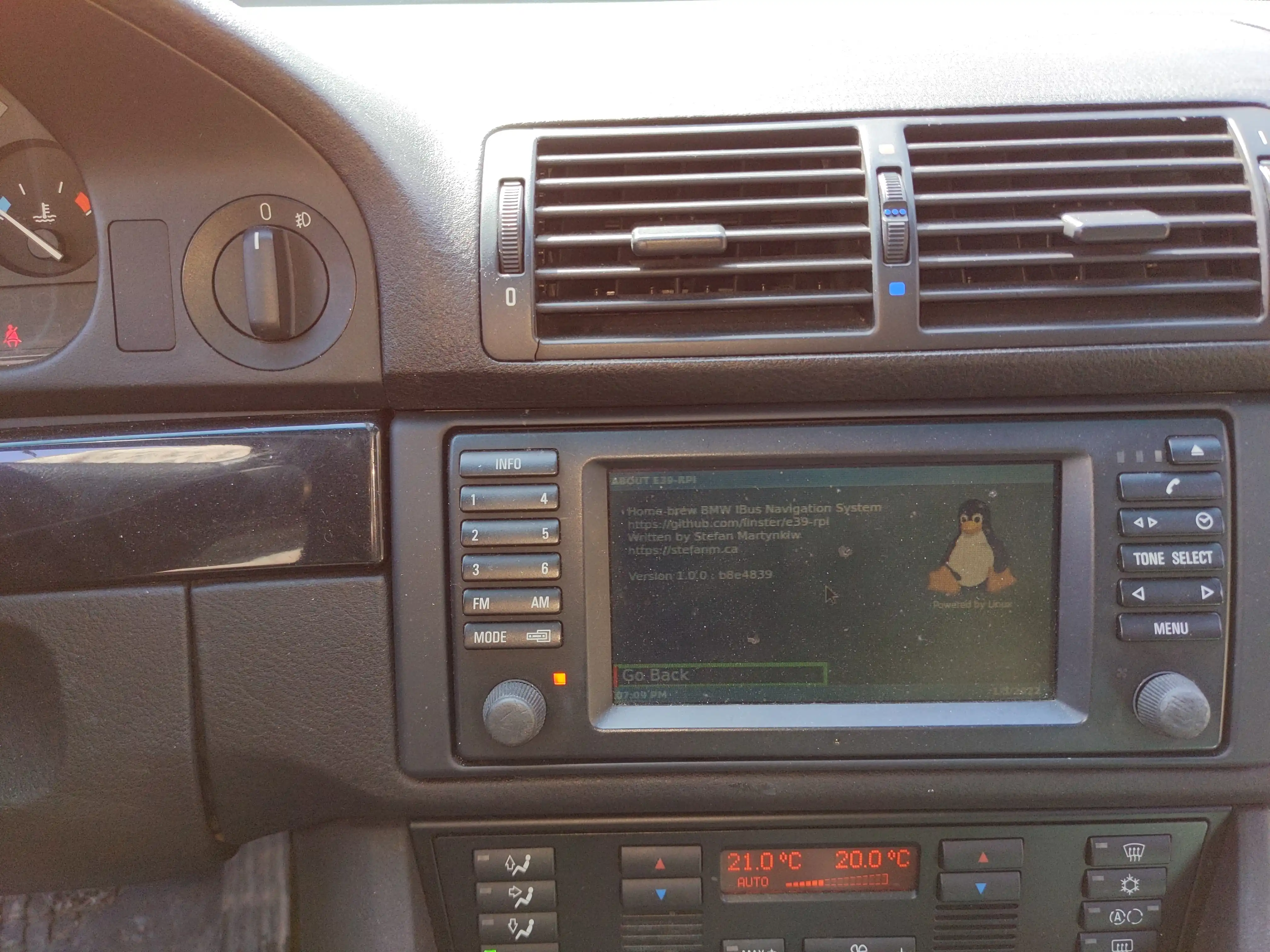
- Update the version.conf file with the git hash. This is shown in the about screen.
- Restart the X server
- Show a live-log of the HMI on the RPI in the laptop’s terminal window.
I set up the Java Debug Wire Protocol flags on the RPi so that I could do remote JVM debugging on my laptop to the instance running on the RPi. This helped me chase after a couple of Pi-only timing bugs in the Matrix chat client.
Future Considerations
I’d like to someday:
- Move the e39-rpi logging from just a logfile in
/home/e39/hmi.logto Journald - Eventually learn more about Yocto Linux.
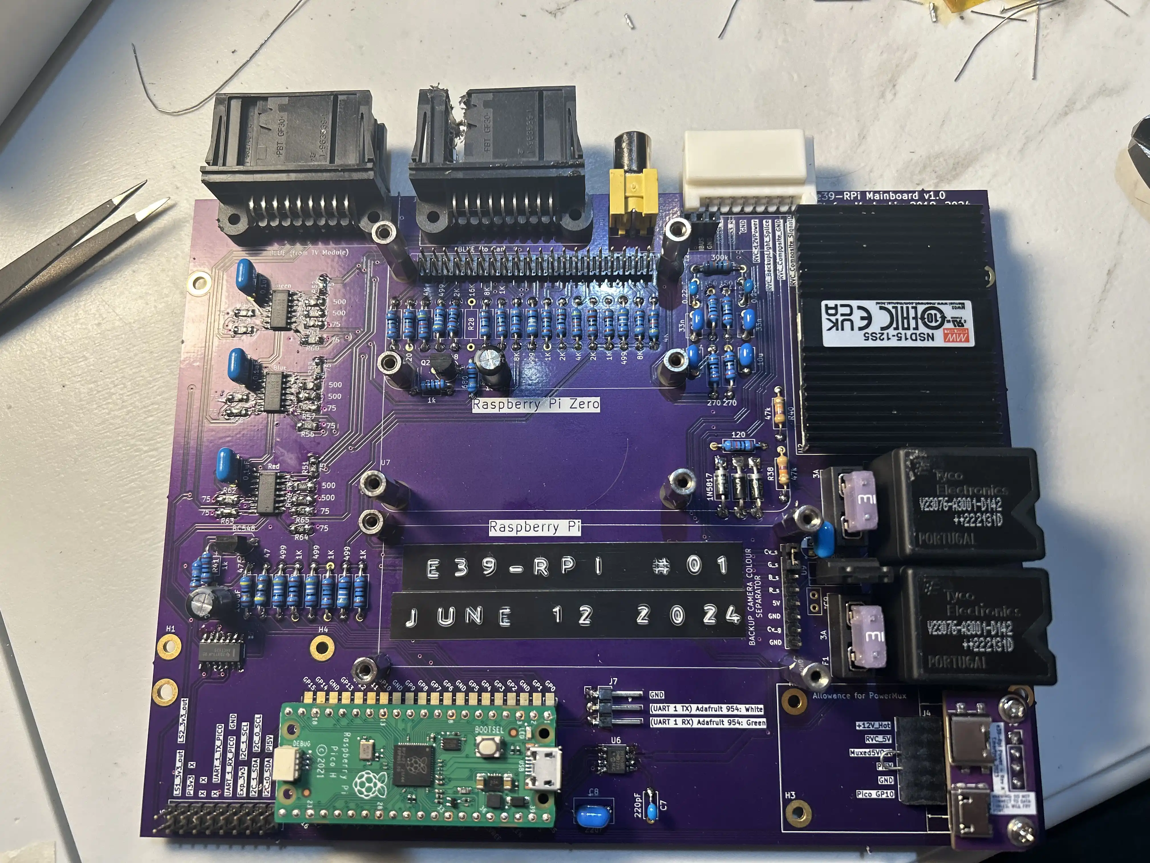
Hardware Design
I designed a custom-board (e39-rpi-mainboard) that incorporates a series of building blocks that I all tested separately.
My hardware prototyping setup consists of:
- Development Laptop
- Development Laptop attached to car
- Test bench
- Development Laptop attached to test bench
- Test “sled”
- Test “sled” attached to my car
- e39-rpi-mainboard boards attached to the test bench
- e39-rpi-mainboard board attached to my car (production environment)
The software protoyping setup works by writing code on a PopOS laptop, which has a similar BlueZ/DBUS environment, allowing rapid local development.
Overview
Development Laptop (& attached to car)
This is where I started the project in September 2020.
Test bench
The test bench is where I started building the hardware for the project. It consists of an IKE instrument cluster, steering wheel buttons, BMBT screen, and wiring via terminal blocks for easy prototyping. I built this so that I didn’t have to sit in the car for extended periods of time writing code.
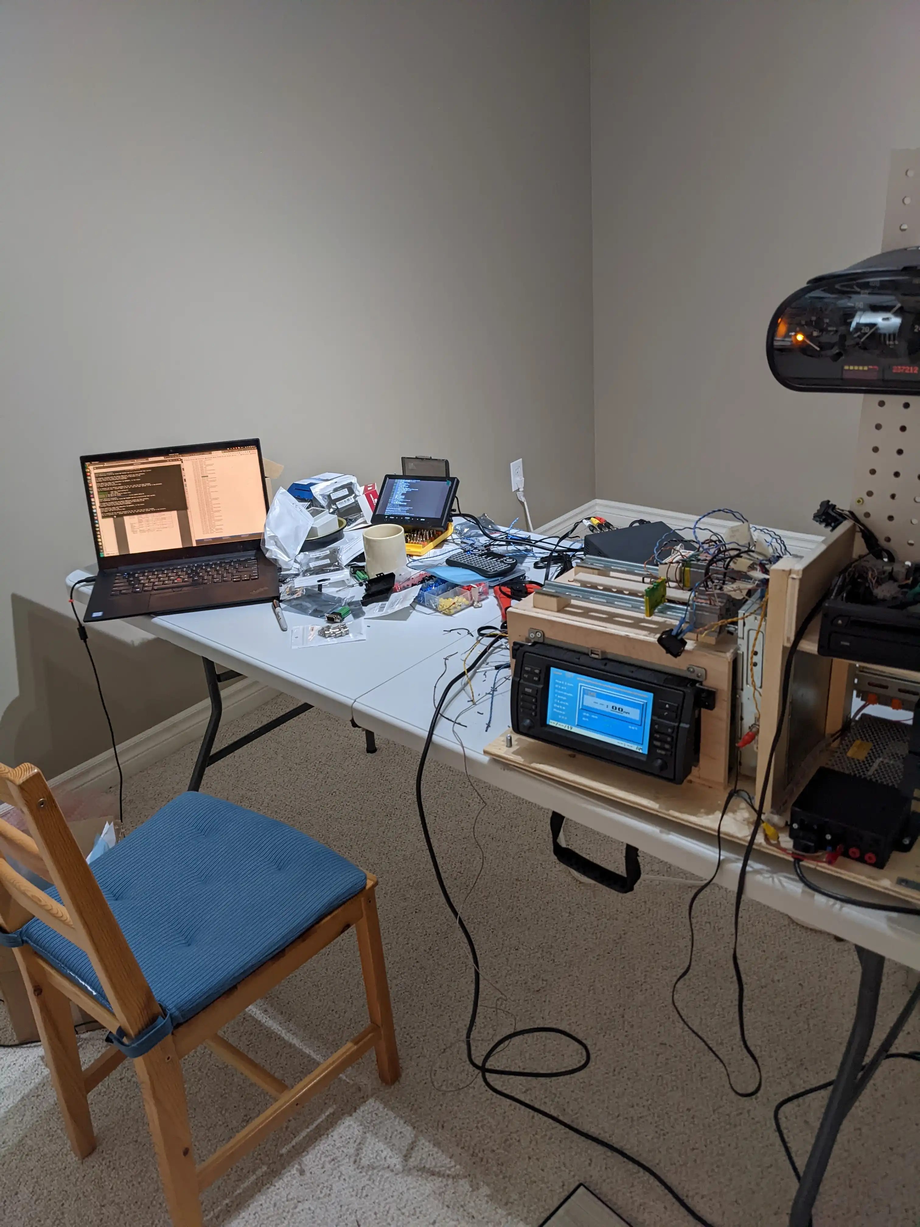
I spent most of 2021-2022 fiddling with the test bench while the pandemic was going on. I made it L-shaped so that I could watch TV with it on my coffee table.
Test sled
I started building the sled after I realized I needed to miniaturize the design.
I needed a way for the RPi power to be turned off and on with the car, and I wanted to reduce the dependency on the European TV Tuner Module.
I build the sled as a precursor to the main-board. The sled contains all the test-boards that make up the main-board. I was able to test the sled in the car
Mainboard
I installed the main-board pictured at the top in a modified MK4 navigation case. The in-car installation is rather tidy.

GitHub Links
ToC
Sitemap (Table of Contents)
- BMW E39-RPi Homebrew Navigation System
- Sitemap
- Pico
- Application Framework
- Inter-device Communications Framework
- Inter-device Logging
- Pico
- Pico Run-time Configuration
- Pico Graphics Library
- IBus
- Observers
- IBus Writers
- Development Environment Setup
- Peripherals
- Hardware
- Hardware
- Test Boards
- Video Output
- Test Bench
- Sled
- Mainboard
- E39-Rpi HMI
- E39-Rpi HMI
- Platform
- Service List
- Platform Service Channels
- Now Playing Screen
- Bluetooth Integration
- Map
- Widget Framework
- Settings
- Debug Screens
- Matrix Chat
- Development Environment
- Pico Interop