This page talks about the PicoToPi and PiToPico messages.
Inter-device Communications Framework
An IBus Packet looks like this:
The Source and Destination device IDs have been documented on the internet before:
WilhelmDocs
I noticed I could borrow the following device IDs
/* Borrow the two MINI D-BUS addresses. */
#define PICO_VALUE 0x31
#define PI_VALUE 0x81
and then put any arbitrary binary message within the data field, and have my own private pico<->pi communications protocol without having to add extra serial or i2c lines on the board! Better still, I could re-use all the existing parsing logic and infra to make it work with minimal changes.
Protobuf
The natural choice for a “small binary format” is protobuf. On the Pico, I used NanoPb with NanoPb_cpp. On the Pi, I used the Google Protobuf implementation for Kotlin/JVM.
Schema
Both pieces of software know of both PicoToPi.proto and PiToPico.proto message formats.
message PiToPico {
  //TODO Someday this could be a union proto type, but not this release.
  enum MessageType {
    EmptyMessage = 0;
    HeartbeatRequest = 1;
    HeartbeatResponse = 2;

    ConfigStatusRequest = 3; //Instruct the pico to tell us what it's config object is
    ConfigPush = 4; //Tell the pico what it's new config object should be

    PicoVideoRequestUpstream = 5; //Ask the pico to show upstream (for Back to BMW function)
    PicoVideoRequestPico = 6; //Ask the pico to show the debug menu
    PicoVideoRequestRpi = 7; //Ask the pico to show the RPi.
    PicoVideoRequestRVC = 8;

    //For test purposes to toggle the power switch for the RPI power supply.
    PicoPowerRequestOn = 9;
    PicoPowerRequestOff = 10;

    //Allow us to simulate ignition events without a GM or LCM or ignition switch
    SimulatedIgnitionPosition0 = 11;
    SimulatedIgnitionPosition1 = 12;
    SimulatedIgnitionPosition2 = 13;
    SimulatedIgnitionPosition3 = 14;
  }

  MessageType messageType = 1;

  ConfigProto newConfig = 2;
}
and
message PicoToPi {
  enum MessageType {
    EmptyMessage = 0;
    HeartbeatRequest = 1;
    HeartbeatResponse = 2;

    //For the logger on the pico to shuttle to Rpi.
    LogStatement = 3;

    //Dump the config object
    ConfigStatusResponse = 4;

    PiSoftPowerRestartX = 5; //Ask the RPI to restart the X server
    PiSoftPowerRestartPi = 6; //Ask the RPI to legit restart
    PiSoftPowerShutdown = 7;
  }

  MessageType messageType = 1;

  oneof body {
    ca.stefanm.e39.proto.ConfigProto configMessage = 2;
    string loggerStatement = 3;
  }
}
Message Categorization
Each direction of message (PiToPico, PicoToPi) contains a MessageType enum that allows the parser logic to switch on the enum value and perform a different action. Reading through some of the enum values, you can see that some messages (ConfigStatusRequest/ConfigStatusResponse for example) make up a two-way request/response protocol.
Heart-beat request/response
There are two types of request/response flows. They can be triggered via the PicoComms test screen in e39-rpi. The observers and writers for each of these are meant to be the barebones test that the stack works.
A tester app/device can spy and inject messages on the bus as either participant.
Pico initiated
Pico Initiated heartbeat request/response:
Pi initiated
Pi Initiated heartbeat request/response:
One-way peripheral messages (PiToPico)
These messages are for sending a message to the Pico to make it do something with its peripherals for test, or business logic purposes.
Video Switch
These messages
    PicoVideoRequestUpstream = 5; //Ask the pico to show upstream (for Back to BMW function)
    PicoVideoRequestPico = 6; //Ask the pico to show the debug menu
    PicoVideoRequestRpi = 7; //Ask the pico to show the RPi.
    PicoVideoRequestRVC = 8;
dispatch a call through Observer to the VideoSwitch
Simulated Ignition (PiToPico)
These messages
    //Allow us to simulate ignition events without a GM or LCM or ignition switch
    SimulatedIgnitionPosition0 = 11;
    SimulatedIgnitionPosition1 = 12;
    SimulatedIgnitionPosition2 = 13;
    SimulatedIgnitionPosition3 = 14;
dispatch a call to Observer
One-way power request (PicoToPi)
These messages
    PiSoftPowerRestartX = 5; //Ask the RPI to restart the X server
    PiSoftPowerRestartPi = 6; //Ask the RPI to legit restart
    PiSoftPowerShutdown = 7;
end up in an observer on the Pi.
Configuration Request/Response
message PicoToPi {
  enum MessageType {
    ...
    //Dump the config object
    ConfigStatusResponse = 4;
    ...
and
message PiToPico {
  enum MessageType {
    ...
    ConfigStatusRequest = 3; //Instruct the pico to tell us what it's config object is
    ConfigPush = 4; //Tell the pico what it's new config object should be
make up the cycle to bring the Configuration object back and forth between the Pi and the Pico.
The Configuration object contains some parameters stored in the Pico’s flash memory for feature flags to use on bootup.
Logging
The coolest part about the whole setup is that Log messages from the Pico can get sent to the Pi.
message PicoToPi {
  enum MessageType {
    ...
    LogStatement = 3;
    ...
  }

  MessageType messageType = 1;

  oneof body {
    ca.stefanm.e39.proto.ConfigProto configMessage = 2;
    string loggerStatement = 3;
  }
}
This is detailed here: Inter-device Logger
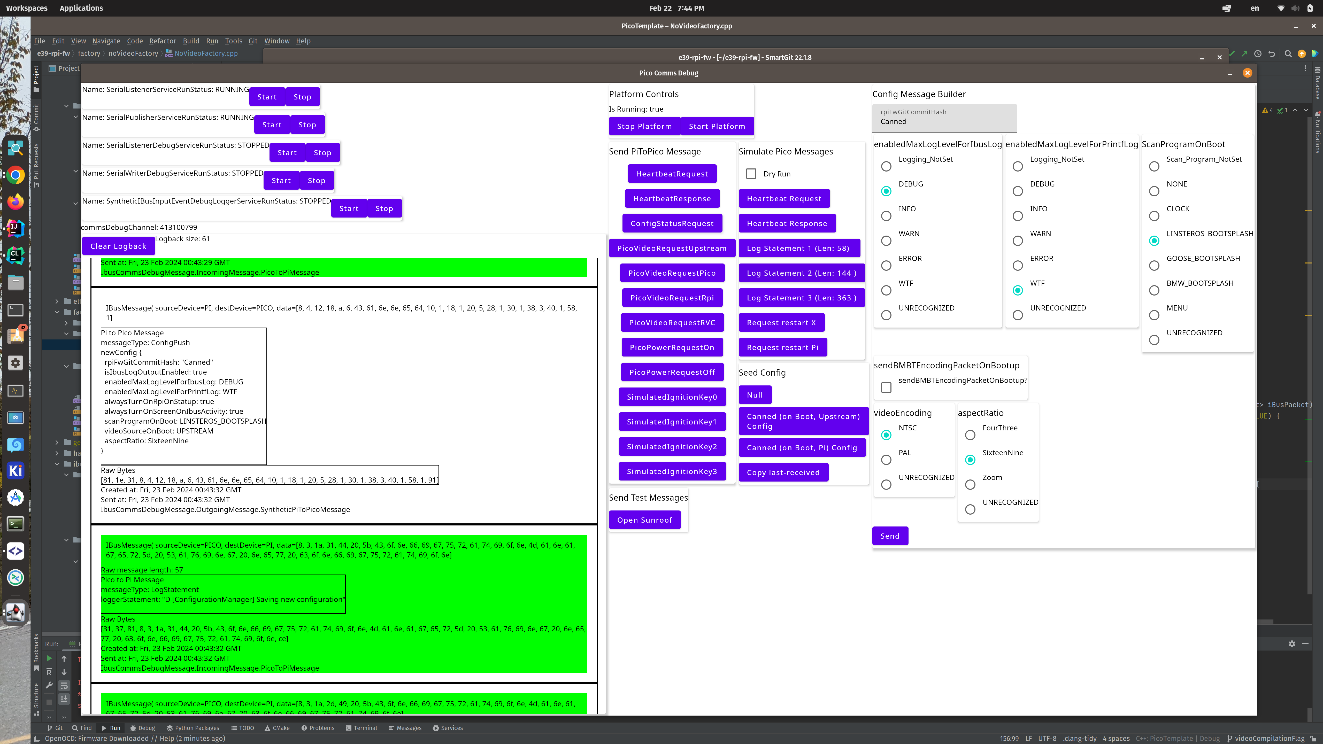
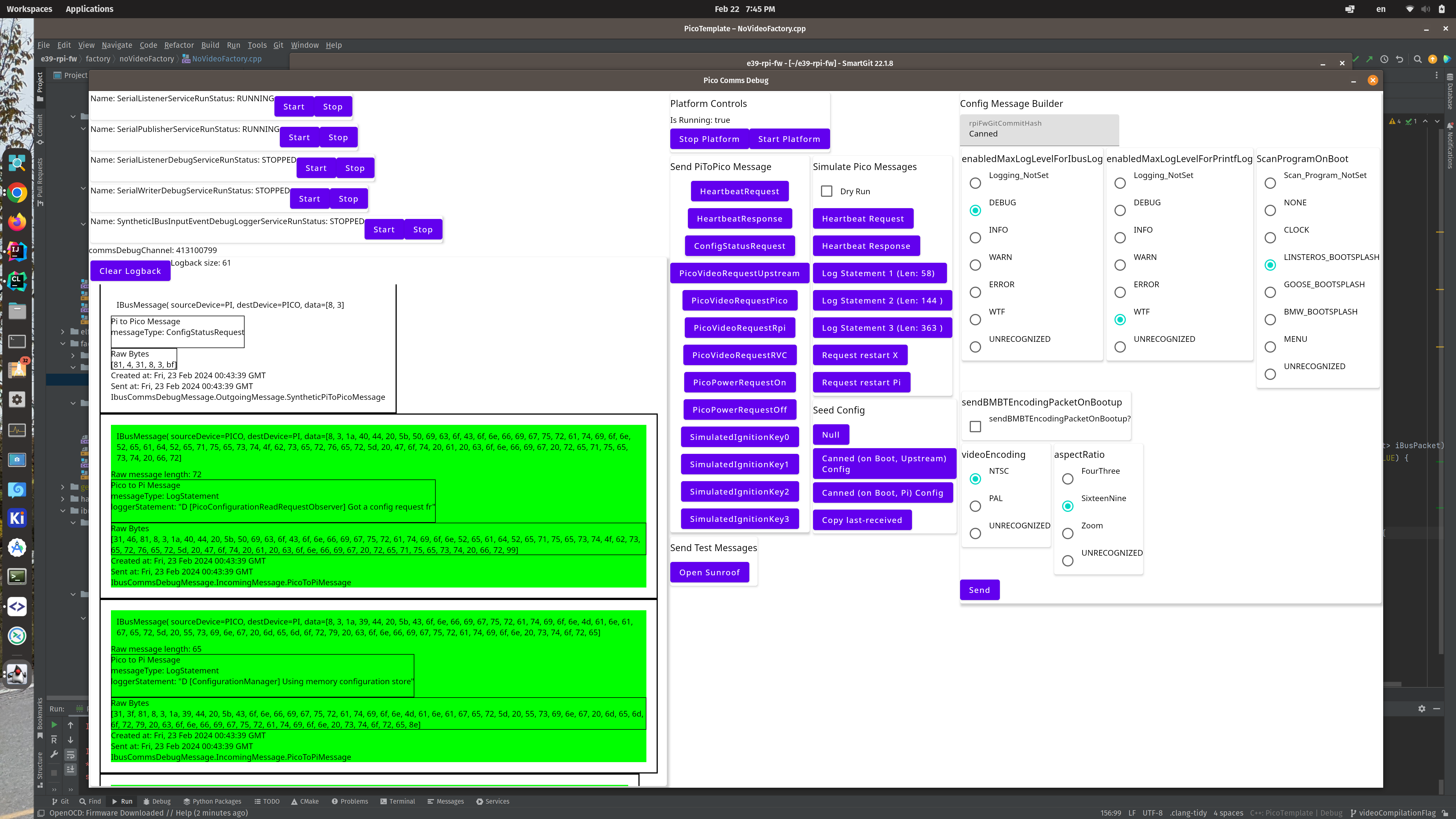
Test tools
The HMI has a Pico Comms debug window. This window lets you:
- View the incoming and outgoing serial bus logs
- See the parsed incoming protobuf messages
- Construct a config object and send it out
- Send some pre-canned PiToPico messages (to stimulate the pico)
- Send some pre-canned PicoToPi messages (to test the Pi side of the message receipt)