
Pico Graphics Library
I wrote a Graphics Library for the Rpi Pico to draw primative lines, rectangles, and fonts. With this library, I then wrote a screen manager.
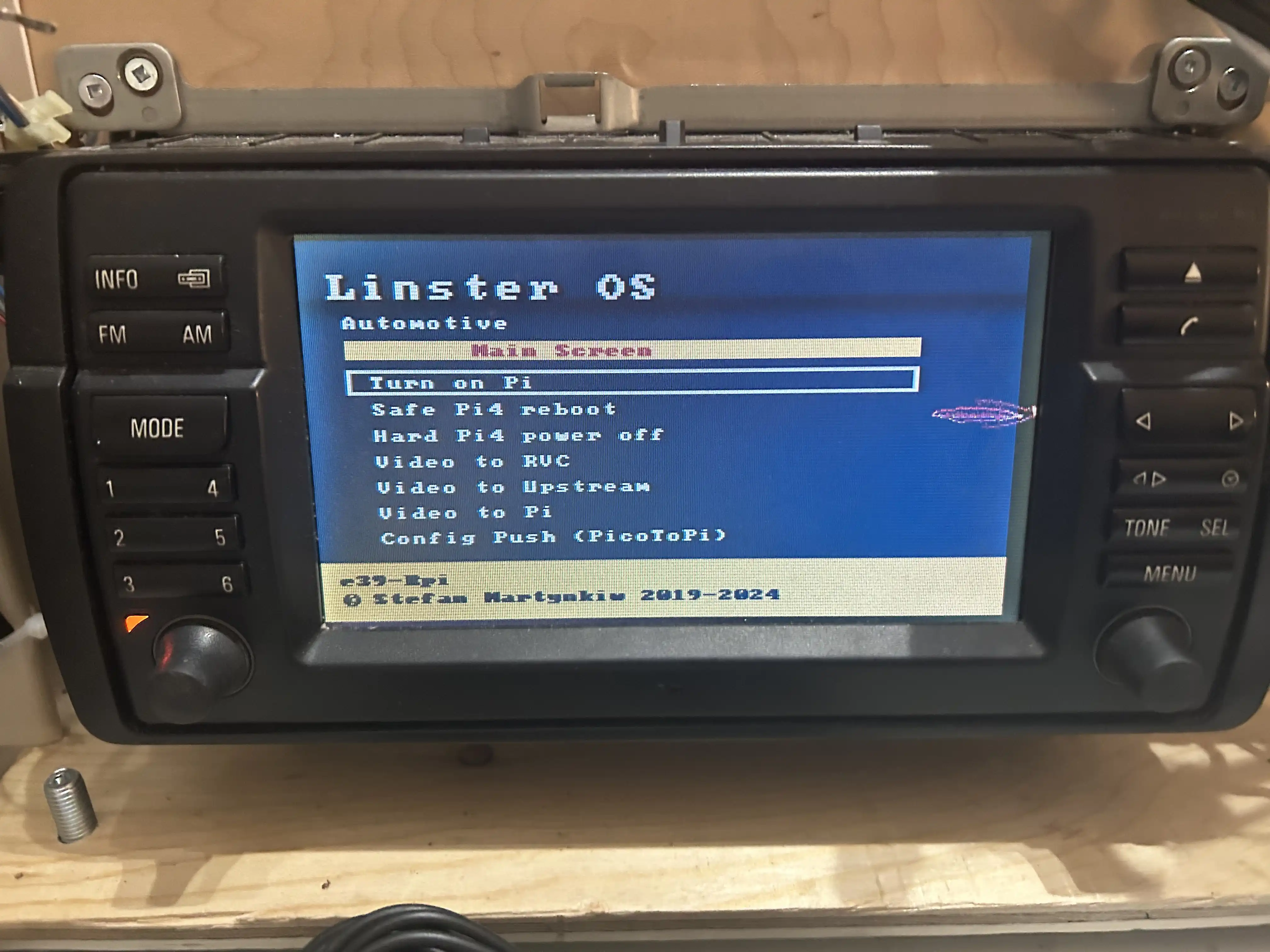
The aim of this part of the project is to allow a “hard-reboot” menu for when the main Rpi locks up. The user can long-press the telephone button to bring up this menu, and do a hard reboot of the main pi.
Screenshot on bench
This shows the completed menu running on the test bench.
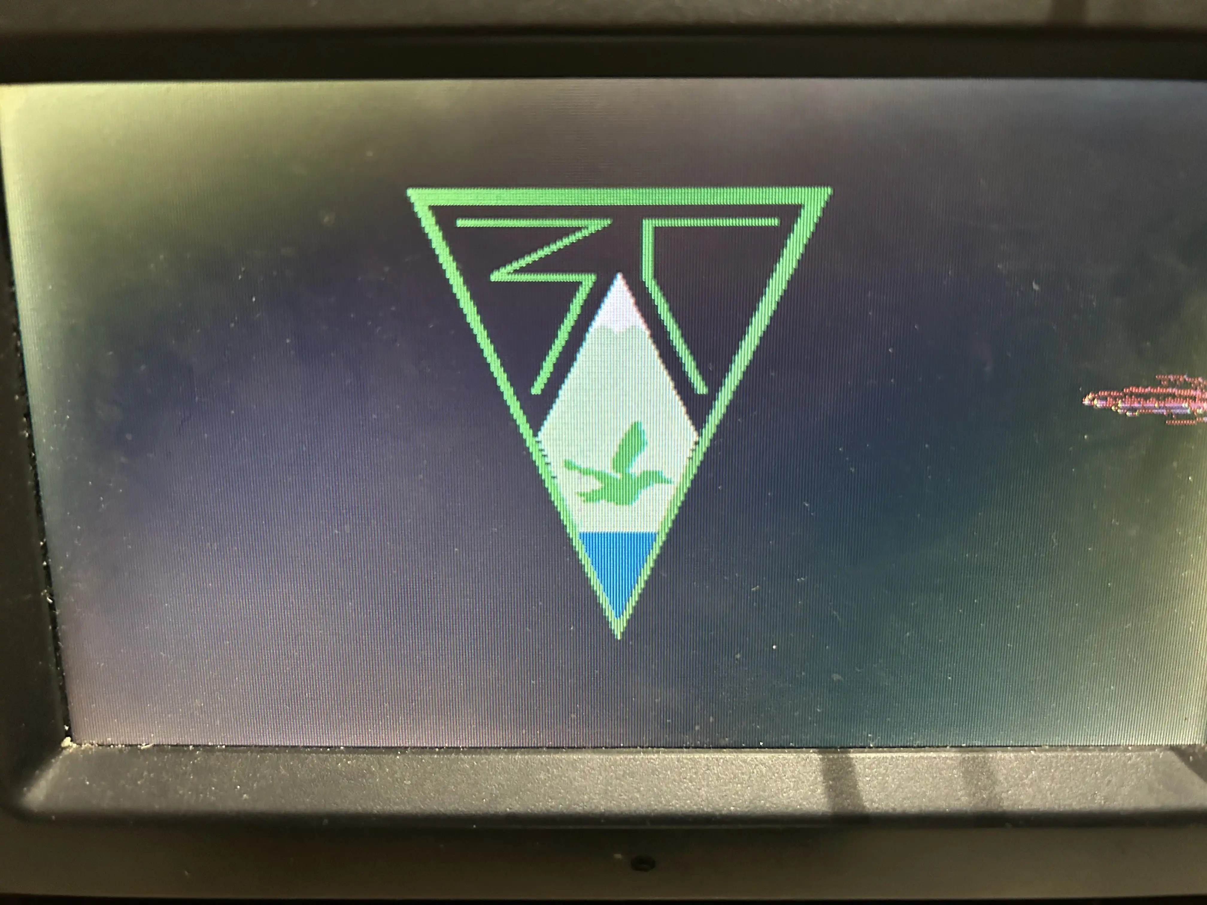
I also made a bootsplash logo of my scout group. It can be enabled by pushing a configuration object to the Pico.
How it works
I used the pico_scan_video library as the base to get graphics output to the display.
First I tested with a simple resistor ladder to VGA, ensured that the example programs worked, then set out to build my own scan program, then a library to make using the scan program easier with the Application Framework I wrote.
The threading model in the ApplicationFramework has the following Arduino-style methods:
    void BaseScanProgram::cpu0setup() {}
    void BaseScanProgram::onCpu0Loop() {}

    void BaseScanProgram::cpu1Setup() {}

    void BaseScanProgram::onCpu1Loop() { callRender();}
Each cpu*setup() method is called once when the CPU starts up. Each onCpu*Loop() is called in a tight while (true) loop on the respective CPU.
Pico Scan Program
The Pico Scan program works by running one of the CPUs in a tight loop to fill in the video scan line data when the PIO DMA is ready for it.
API docs talks about how the scan program is used.
BaseScanProgram shows how the application framework calls CPU0 on a tight loop to fill in the scanline.
The tight loop looks like this:
while (true) {
    // get the next scanline buffer that needs filling, blocking if we're to far ahead
    scanvideo_scanline_buffer_t *scanline_buffer = scanvideo_begin_scanline_generation(true);

    // scanline_buffer->scanline_id indicates what scanline you are dealing with

    // scanvideo_frame_number(scanline_id) tells you the (16 bit) frame number
    // scanvideo_scanline_number(scanline_id) tells you the scanline number within the frame

    // ---------------------------------------------------------------------------
    // code goes here to fill the buffer... (see Generating Content section below)
    // ---------------------------------------------------------------------------

    // pass the completed buffer back to the scanvideo code for display at the right time
    scanvideo_end_scanline_generation(scanline_buffer);
}
The Scan Program requires filling in a scanline struct with a bunch of tokens to indicate:
- One pixel of a particular color
- Two pixels of a particular color
- N pixels of a particular color
This makes drawing primitives to the screen difficult: How do you manage, on a per-scanline basis, what “runs” of pixel colours you want? That’s where the Graphics Library comes in.
To get there, I first had to prove that I had setup the scan program correctly, by just outputting solid scan lines. I could get rudimentary shapes by switching the colour based on the line number.
The current example code lives in DemoScanProgram. Later I’ll show how the system supports multiple scan programs to allow swapping between a debug menu for messing around with the graphics lib, the menu, and a boot splash screen.
First, let’s look at the DemoScanProgram.
I made a base class BaseScanProgram whose most important methods are:
    void DemoScanProgram::onScanProgramStart() {
        logger->d(getTag(), "onScanProgramStart()");
        //setupComputedFrame();
    }

    void DemoScanProgram::onScanProgramStop() {
        logger->d(getTag(), "onScanProgramStop()");
    }

    void DemoScanProgram::render(scanvideo_scanline_buffer_t *scanline_buffer) {
        //render_flag_ua(scanline_buffer);
//        render_text(scanline_buffer);

        render_solid_screen(scanline_buffer);
//        render_computedFrame(scanline_buffer);
    }
I built up the demo in the next section in phases:
- No matter what the current line number is, fill
scanline_bufferwith the tokens to show a solid color line - Switch on the current line number to fill
scanline_bufferwith the tokens to show a line of different colour based on the vertical position in the frame. This is how I drew the Ukrainian flag below. - Start writing a graphics library that has a function (
render_computedFrame()) that can fill in ascanline_buffergiven an input of the current line number. - Use the
onScanProgramStart()hook to then fill in the data structure in the graphics library so that therender_computedFrame()method can give a scanline whose contents is part of the frame.
Building up the Pico scan program and graphics library
Ukrainian Flag Demo
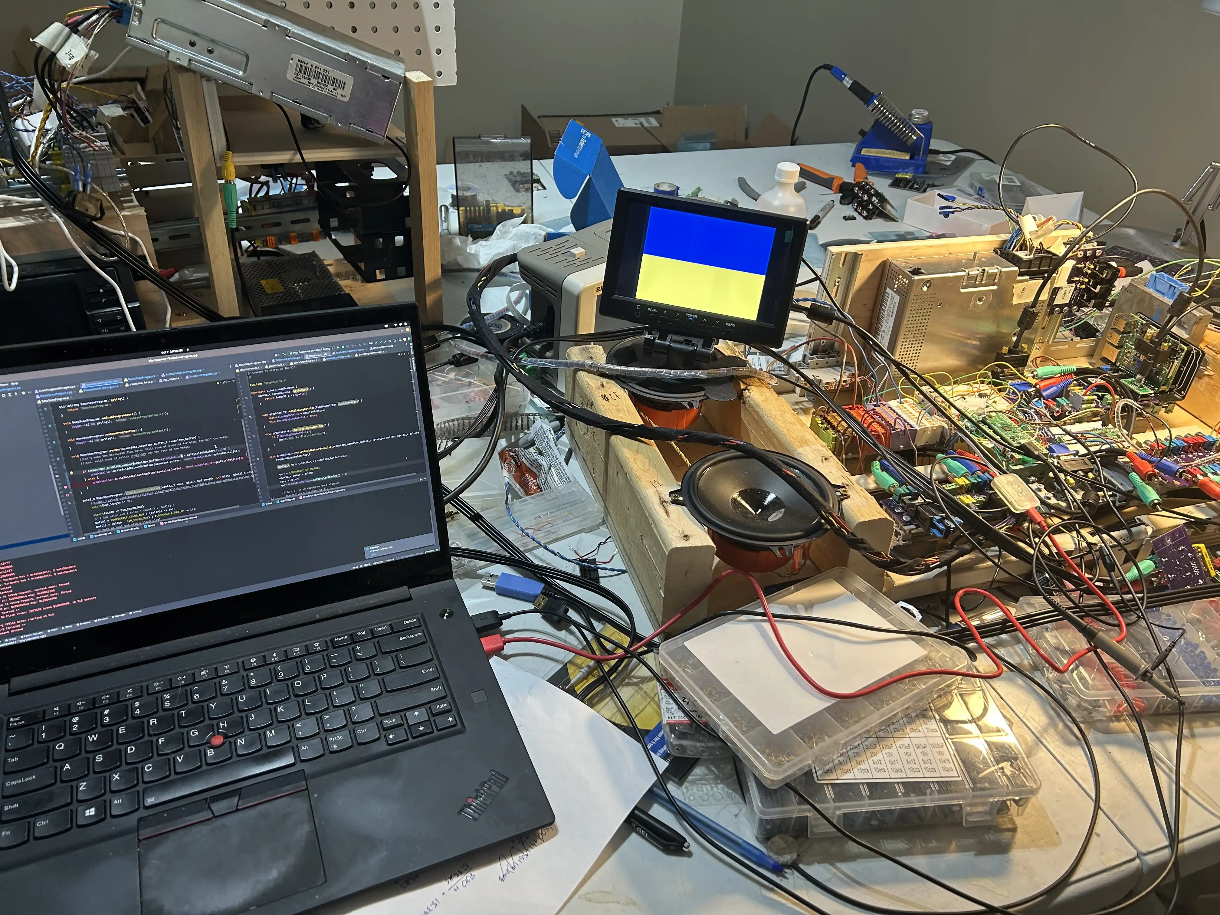
This picture shows a Ukrainian Flag. The top half is blue, and the bottom is yellow.
    void DemoScanProgram::render(scanvideo_scanline_buffer_t *scanline_buffer) {
        render_flag_ua(scanline_buffer);
    }
    void DemoScanProgram::render_flag_ua(scanvideo_scanline_buffer_t *scanline_buffer) {
        //Let's make the Ukrainian flag here. Solid runs of scanline for blue, for half the height
        //Then, solid runs of yellow scanlines for the rest of the height.
        if (scanvideo_scanline_number(scanline_buffer->scanline_id) < getDisplayHeightPx() / 2) {
            graphicsLib->writeSolidColourScanline(scanline_buffer, graphicsLib->getPalette()[3]);
        } else {
            graphicsLib->writeSolidColourScanline(scanline_buffer, graphicsLib->getPalette()[14]);
        }
    }
Here we see the scan program is only using the graphicsLibrary just to fill in the buffer for the scanline. The render() method is just dispatching to a method (render_flag_ua()) that just fills in the scanline into the out-parameter provided.
Writing out the solid colour scanline looks like this:
    void graphicsLib::writeSolidColourScanline(scanvideo_scanline_buffer_t *scanline_buffer, uint32_t colour) {
        requireDisplayMetrics();

        uint16_t *p = (uint16_t *) scanline_buffer->data;

        *p++ = COMPOSABLE_COLOR_RUN;
        uint32_t color = colour;
        *p++ = color;
        *p++ = displayMetrics.getDisplayWidthPx() - 3;

        // 32 * 3, so we should be word aligned
//        assert(!(3u & (uintptr_t) p));

        // black pixel to end line
        *p++ = COMPOSABLE_RAW_1P;
        *p++ = 0;
        // end of line with alignment padding
        *p++ = COMPOSABLE_EOL_SKIP_ALIGN;
        *p++ = 0;

        scanline_buffer->data_used = ((uint32_t *) p) - scanline_buffer->data;
        assert(scanline_buffer->data_used < scanline_buffer->data_max);

        scanline_buffer->status = SCANLINE_OK;

    }
Graphics Library Demo

I re-used the DemoScanProgram to add support for the graphics library.
    void DemoScanProgram::onScanProgramStart() {
        logger->d(getTag(), "onScanProgramStart()");
        setupComputedFrame();
    }

    void DemoScanProgram::onScanProgramStop() {
        logger->d(getTag(), "onScanProgramStop()");
    }

    void DemoScanProgram::render(scanvideo_scanline_buffer_t *scanline_buffer) {
        render_computedFrame(scanline_buffer);
    }
    void DemoScanProgram::render_computedFrame(scanvideo_scanline_buffer_t *scanline_buffer) {
        graphicsLib->render_commandProcessed(scanline_buffer);
    }
    void DemoScanProgram::setupComputedFrame() {

        graphicsLib->drawEmptyRectangle(
                scanVideo::graphics::command::PxCoord(10,10),
                scanVideo::graphics::command::PxCoord(30,30),
                graphicsLib->getPalette()[14],
                1
        );
        /// More commands here
    }
The above code-snippet shows the graphics library works in a “two-phase” manner of operation:
- Set up a “computed frame”. This means placing a bunch of drawing commands into a command list.
- Compute the frame (part 1). Loop over the drawing commands and have each one contribute to a
Map<LineNumber, RleRun> - Compute the frame (part 2). Squish the map. Transform
Map<LineNumber, RleRun>intoMap<LineNumber, Scanline_Buffer_t>. - Start the scan program, which allows
render()to read theComputed Frame (part 2).
There are some optimizations made in the code to allow skipping or bypassing recomputations of the frame (see some of the setters for ImmediateMode), but it’s all one big flow contributing to populating the above data structures.
Graphics Library Commands
Structure
Every BaseCommand is placed onto a command list. The CommandProcessor is responsible for the computation steps described above.
The GraphicsLibrary class wraps the CommandProcessor so that the CommandProcessor can be swapped out for a more efficient one (less memory usage) without affecting the GraphicsLibrary API surface.
BaseCommands
Every command implements the BaseCommand interface.
namespace video::scanVideo::graphics::command {
    class BaseCommand {
    public:
        //An inclusive range of affected scanlines
        virtual std::pair<uint16_t, uint16_t> getAffectedScanlines() = 0;

        //Each command contributes an ordered RLE run for a scanline.
        virtual std::map<uint16_t, std::vector<RleRun>> getRleRunsForShape() = 0;

        virtual ~BaseCommand() = default;
    };

}
Each BaseCommand holds a map of RleRuns, where the key is the scanline, and the value is a vector of RleRuns.
This is mostly a wrapper on a triple with some utility methods.
namespace video::scanVideo::graphics::command {

    class RleRun {

    private:

        uint16_t startX = 0;
        uint16_t len = 0;
        uint32_t colour = 0;
    public:

        RleRun(
                uint16_t startX,
                uint16_t len,
                uint32_t colour
                );

        uint16_t getStartX();

        uint16_t getLen();
        void setLen(uint16_t newLen);

        uint32_t getColour();
        void setColour(uint32_t colour);

        RleRun appendSameColor(RleRun other);

    };

} // command
Example: Empty Rectangle Command
The EmptyRectangleCommand is the simplest “interesting” command.
An empty rectangle is defined as one that is not filled. It has a top left pixel coordinate, a width, a height, and a thickness property. Geometrically, this means:
Thicknessnumber of “top lines”, running the with of the rectangle, from the top-left- On an “inner-line” (of which there are height - 2*thickness), a left run (of len thickness) at the start
- On an “inner-line”, a right run at the end (of len thickness)
- And
thicknessnumber of “bottom lines”
In code, this looks like:
std::map<uint16_t, std::vector<RleRun>> EmptyRectangleCommand::getRleRunsForShape() {
        std::map<uint16_t, std::vector<RleRun>> returnMap = std::map<uint16_t, std::vector<RleRun>>();

        uint16_t len = bottomRightPx.getX() - topLeftPx.getX();

        for (int i = topLeftPx.getY(); i <= bottomRightPx.getY(); i++) {
            std::vector<RleRun> runForLine = std::vector<RleRun>();

            if (i == topLeftPx.getY()
                    || i < topLeftPx.getY() + lineWidth
                    || i == bottomRightPx.getY()
                    || i > bottomRightPx.getY() - lineWidth
                ) {
                runForLine.push_back(RleRun(
                        topLeftPx.getX(),
                        len,
                        colour
                ));
            } else {
                runForLine.push_back(RleRun(
                        topLeftPx.getX(),
                        lineWidth,
                        colour
                ));
                runForLine.push_back(RleRun(
                        bottomRightPx.getX() - (lineWidth),
                        lineWidth,
                        colour
                ));
            }
            returnMap[i] = runForLine;
        }
        return returnMap;
    }
Memory consumption calculation
The space complexity of this shape could be measured:
- RleRun * thickness * 2 for the top and bottom lines
- Two RleRuns for each inner line
There’s some book-keeping info, but the whole system only has 256kb of ram. To fill a rectangle like above would take (at worst, for the full size of screen) the amount of memory in the following calculation.
Screen height: 234 lines. Screen width: 400 pixels.
Let’s assume a thickness of 2. Number of RleRuns for the top and bototm lines: 4 Number of RleRuns for the middle lines: 2 * 200 = 400.
That makes 434 RleRuns in total. Each RleRun holds two int16’s and one int32, which makes for 8 bytes.
That makes 3472 bytes (3.4kb) in book keeping information for this rectangle. The start and end line nubbins really make this way more inefficient than it could be. If this were a solid rectangle, we would only need 234 RleRuns (one per scanline).
Still, this is much less space taken up than the equivalent framebuffer, which would be 400*234 * 1 byte per pixel of color info = 93600 bytes.
This calculation shows that RLE encoding of the graphics data greately favours solid colours, no striped patterns. If you were to do a Classic Mac OS pattern, you’d probably be worse-off than having a framebuffer. Using up > 1/2 of the memory for a frame buffer means there might not be enough ram for the rest of the system to run.
Concrete Commands
The following is a list of all the commands I implemented. Their source can be read in the e39-rpi-fw repo.
- EmptyRectangle
- FilledRectangle
- Line
- RleContainer
- Text
Line
The Line command uses Bresenham’s Line Algorithms to draw vertical, horizontal, and diagonal lines. I had some serious deja-vu writing this, because in my 2016 University Capstone Project, I wrote these in VHDL as custom CPU instructions for the Altera Nios/II CPU.
RleContainer
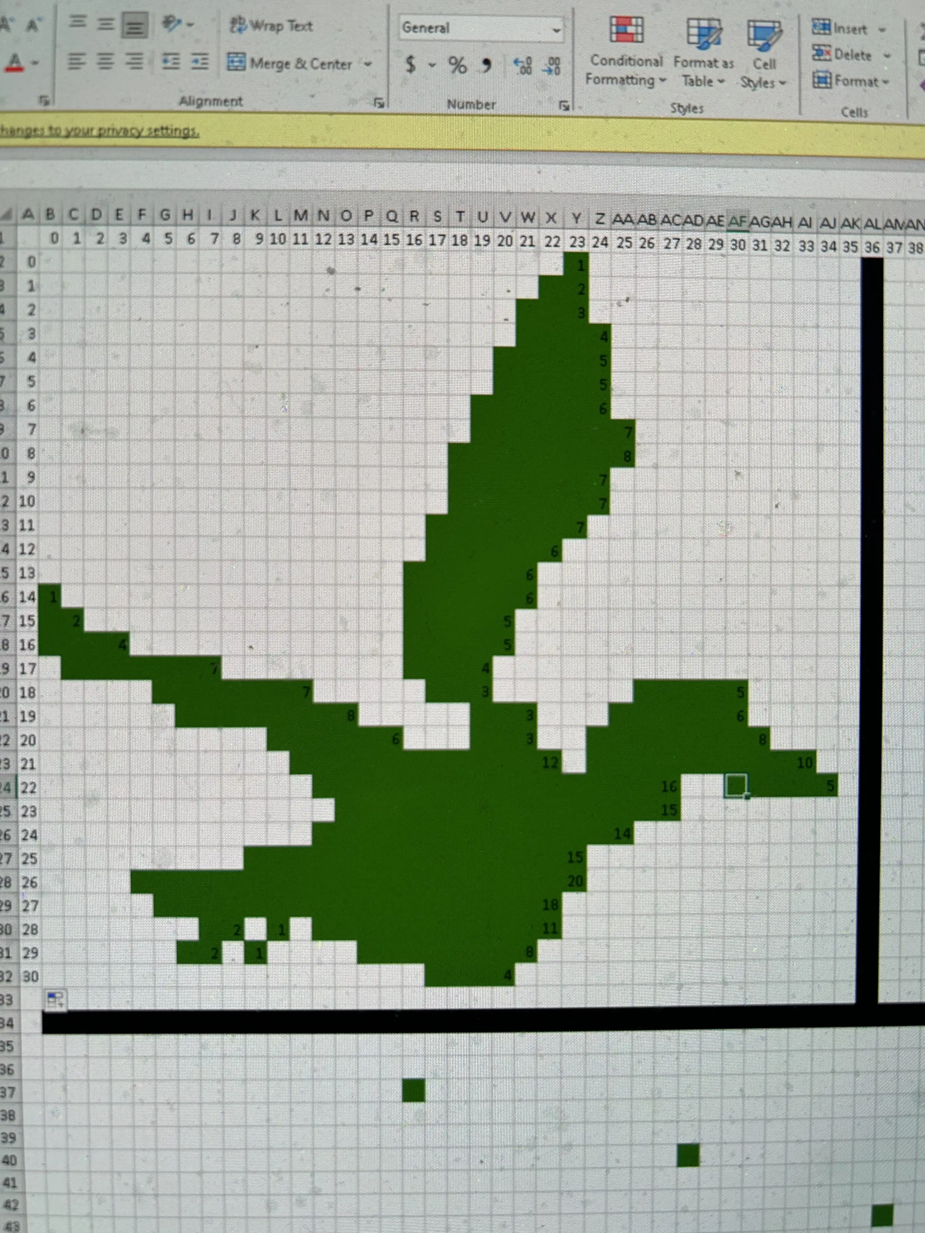
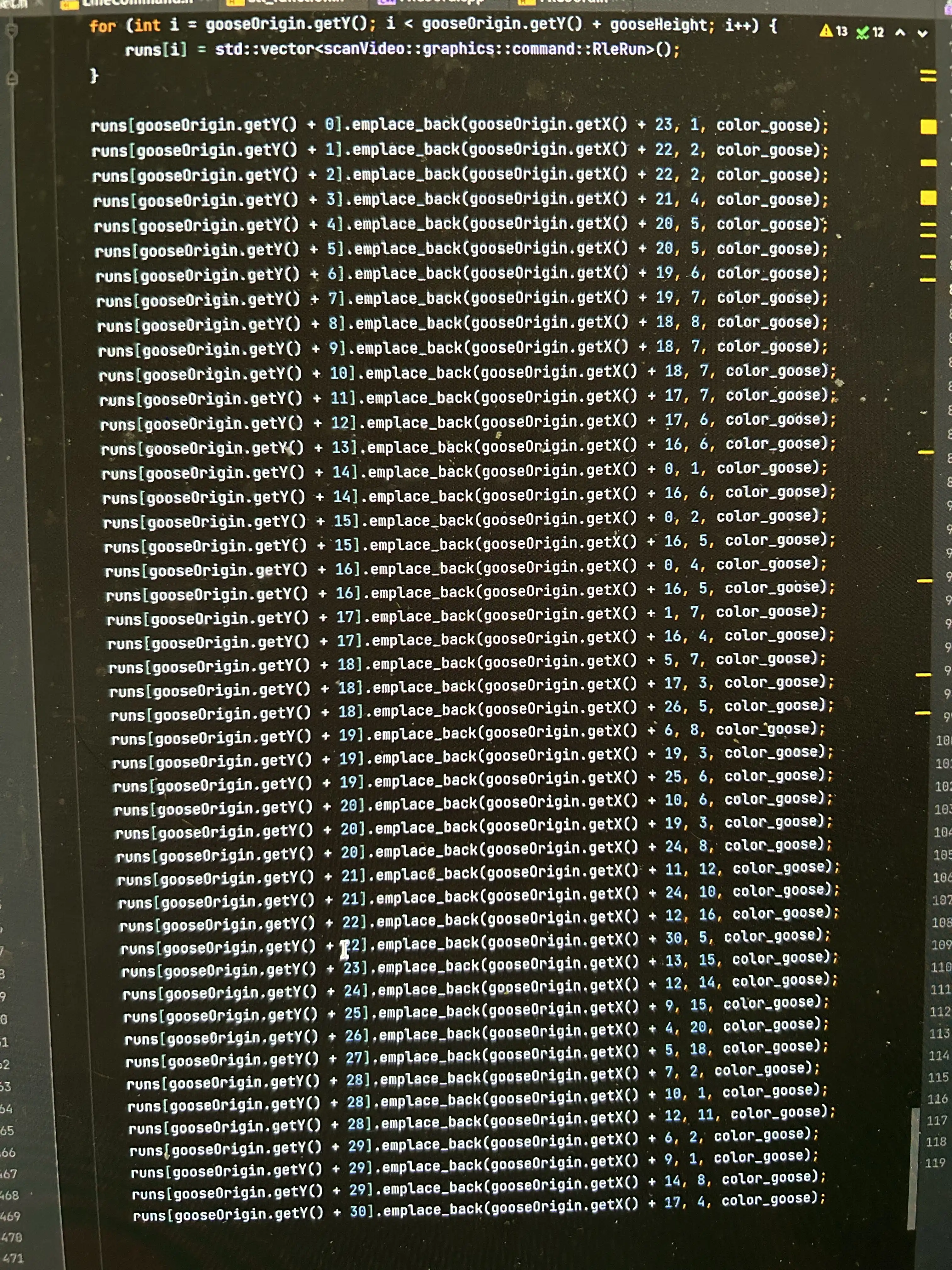
This one’s a bit of an API hack for the CommandProcessor. I needed a way to contribute something like a bitmap (but not actually a bitmap) into the internal data structures in the command processor. I used this for the bird in the scout logo. I sketched out the logo bitmap in Excel, (dat pixel art yo) and hand-wrote the Map<LineNumber, RleRun> map to draw it to screen.
Text
This one was fun. I found a public domain IBM PC BIOS font which had each letter as 2d array of bits. For each cell in the array, I draw a filled rectangle for the “pixel”. The command takes in a c_str, loops over the chars, loops over the cells in the 2d array that are set to 1, then creates more DrawFilledRectangle commands.
CommandProcessor
The CommandProcessor is where all the good stuff happens.
The API of the graphics library works in a “two-phase” manner of operation:
- Set up a “computed frame”. This means placing a bunch of drawing commands into a command list.
- Compute the frame (part 1). Loop over the drawing commands and have each one contribute to a
Map<LineNumber, RleRun> - Compute the frame (part 2). Squish the map (merge the scanlines). Transform
Map<LineNumber, RleRun>intoMap<LineNumber, Scanline_Buffer_t>.
Each of these steps have intermediate results held in the following data structures:
        std::vector<std::unique_ptr<BaseCommand>> commandsToProcess;
        std::map<uint16_t, std::vector<RleRun>> rleRunsToProcess;
        /**
         * Key is scanline number.
         * Value is a vector<RleRun> where no runs overlap, all runs sorted in ascending order
         * of startX. Can be looped over in drawScanline
         */
        std::map<uint16_t, std::vector<RleRun>> rleRunsForLine;
Once the computation is complete, the commandsToProcess and the rleRunsToProcess variables can be cleared to save on memory.
Processing Commands
Each command implements BaseCommand which allows the following code to work:
    //Called from CPU0
    void CommandProcessor::addCommand(std::unique_ptr<BaseCommand> baseCommand) {
        for (const auto g : baseCommand->getRleRunsForShape()) {
            if (rleRunsToProcess.count(g.first) == 0) {
                rleRunsToProcess[g.first] = std::vector<RleRun>();
            }
            for (const auto gp : g.second) {
                rleRunsToProcess[g.first].push_back(gp);
            }
        }

        if (isImmediateMode) {
            computeFrame();
        }
    }
The index to rleRunsToProcess is the scanline number, and the value is a vector of RleRuns.
Merging RleRuns
Each line has RleRuns that exist from different shapes. The next step is to compress each line.
For example, on a particular line, you could have runs like
XXX YYY ZZZ
3X   3Y  3Z
and if the runs represented by X, Y, and Z are the same color, the line could be compressed to
XXX_XXX_XXX
9X
The mergeRuns() method handles this compression with the following steps:
- Make a line buffer that is as long as the screen is wide.
std::array<uint32_t, maxDisplayWidth> lineBuffer; - For each RleRun, dump its colors into the
lineBuffer - Loop over the
lineBufferand make avector<RleRun>for the line, compressed.
I originally thought of doing this without a lineBuffer. The idea was to sort the RleRuns by ascending startX, then squish/merge/etc. I figured the time and space complexity of this was worse in most cases than taking 2*O(n) time and O(n) complexity by using a lineBuffer.
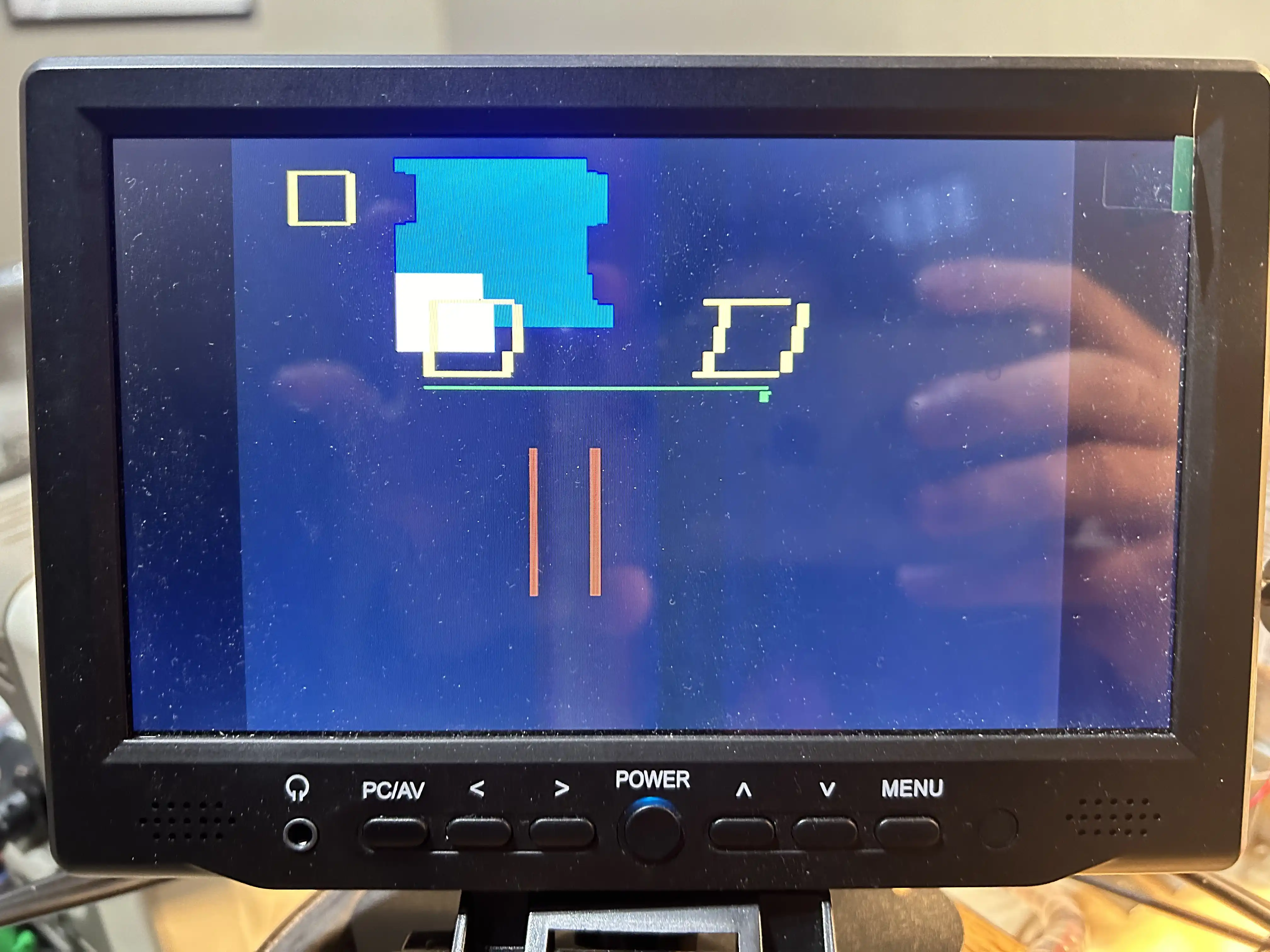
I had some trouble when I wrote the mergeRuns() method with off-by-one errors. The picture below shows what the graphics output looked like with a handful of off-by-one errors.
BaseColor space optimization
Drawing a filled rectangle to get a background colour on the screen makes the mergeRuns slower in most cases. So, to save on space, I set a baseColor so that the intermediate data structures don’t need the time and space to hold RleRuns for just the background colour.
This allows sparse screens with few commands to minimize computations in processing and merging.
The render_computed() method makes use of this optimization to draw a solid color scanline when there are no shapes on a line.
Converting a merged vector to a scanline_buffer
This is where I use the pico_scanout_video example code to write into the scanline buffer.
    //Called from CPU1
    void CommandProcessor::drawScanline(
            scanvideo_scanline_buffer_t *scanline_buffer,
            std::vector<RleRun> merged) {

        //We assume the `merged` vector is sorted and has no duplicates by
        //the time we get here.

        uint16_t *p = (uint16_t *) scanline_buffer->data;

        for (auto run : merged) {
            if (run.getLen() == 1) {
                *p++ = COMPOSABLE_RAW_1P;
                *p++ = run.getColour();
            }
            if (run.getLen() == 2) {
                *p++ = COMPOSABLE_RAW_2P;
                *p++ = run.getColour();
                *p++ = run.getColour();
            }
            if (run.getLen() >= 3) {
                *p++ = COMPOSABLE_COLOR_RUN;
                *p++ = run.getColour();
                *p++ = run.getLen() - 3;
            }
        }

        // black pixel to end line
        *p++ = COMPOSABLE_RAW_1P;
        *p++ = 0;
        // end of line with alignment padding
        *p++ = COMPOSABLE_EOL_SKIP_ALIGN;
        *p++ = 0;

        scanline_buffer->data_used = ((uint32_t *) p) - scanline_buffer->data;
        assert(scanline_buffer->data_used < scanline_buffer->data_max);

        scanline_buffer->status = SCANLINE_OK;
    }
Render Method
This is where the baseColor optimization and the mergedRuns are written out to the screen.
    //Called from CPU1
    void CommandProcessor::render_computed(scanvideo_scanline_buffer_t *scanline_buffer) {
        if (!this->isFrameComputed) {
            skipScanline(scanline_buffer);
            return;
        }
        uint16_t line_num = scanvideo_scanline_number(scanline_buffer->scanline_id);

        if (rleRunsForLine.count(line_num) == 0 && baseColour != 0) {
            drawSolidColorScanline(scanline_buffer, baseColour);
            return;
        }

        if (rleRunsForLine.count(line_num) == 0) {
            //No command has artifacts for the line, so skip it
            //Fill colour should have already been drawn here
            skipScanline(scanline_buffer);
        } else {
            //We have a scanline to draw
            drawScanline(scanline_buffer, rleRunsForLine[line_num]);
        }
    }
GraphicsLib API Shim
The GraphicsLib acts as a shim over top of the CommandProcessor. It also provides higher level commands.
Primitive Commands
Most primitive commands look like this:
    void graphicsLib::drawEmptyRectangle(scanVideo::graphics::command::PxCoord topLeftPx,
                                         scanVideo::graphics::command::PxCoord bottomRightPx, uint32_t colour,
                                         uint8_t lineWidth) {


        std::unique_ptr<scanVideo::graphics::command::EmptyRectangleCommand> ptr =
                std::make_unique<scanVideo::graphics::command::EmptyRectangleCommand>(topLeftPx, bottomRightPx, colour, lineWidth);

        addCommandToFrame(std::move(ptr));
    }
    /// More commands here
    void graphicsLib::addCommandToFrame(std::unique_ptr<scanVideo::graphics::command::BaseCommand> command) {
        commandProcessor->addCommand(std::move(command));
    }
This technique allows the calling API surface to be a little cleaner.
Compound Commands
I implemented drawDelta() (equilateral or iscosceles triangle with flat edge on bottom) and drawNabla() (an equilateral or isosceles triangle with flat edge on top) in the GraphicsLib by having the GraphicsLib add a bunch of commands to the CommandProcessor.
These commands are pretty space and time inefficent, but they’re only used on the scout bootsplash.
MenuScanProgram
After I could display what looked like a static menu, the next step was to wire up some logic to make the screen react to knob turn events.
First, I needed to represent the data on the screen, and see that the knob turn events could change which of the screen items was selected. I debugged this logic and application structure by bypassing the drawing logic temporarily, and wrote out the current menu state as as series of log messages to the main system log (Which is readible on the serial bus).
Text Screen Output
The screen state debug logs are shown below.

Representing the data structure for a screen.
Screen and ScreenItem classes
A ScreenManager is composed of one or more Screens. A Screen contains one or more ScreenItems.
When a ScreenItem is focused, a boolean is set on it.
I chose to use the composite pattern for each ScreenItem so that each ScreenItem holds a reference to the object it wants to call a method on.
I similarly made Screen hold (compose) ScreenItems so that I can move ScreenItems around between screens with minimal refactoring. When the dependency injection is hand-written, these optimizations for less typing make the code easier to write.
Screen Items
Video Switch Items
These items instruct the video switch to change it’s input.
PicoToPi ScreenItems
These messages send a PicoToPi message.
RestartX
This message is intended to tell the RPi to restart its X server. This is for when the Jebrains Compose HMI locks up and can’t respond to knob turn events.
Soft Power Off
This message is received by the RPi, and when it is received the RPi should shut itself down safely. It is sent by the Pico when the ignition key is turned indicating the user is ready to stop driving.
Power Switch
HardPi4PowerOff
This forcefully cuts the power to the RPi.
TurnOnPi4
This turns on the power supply on the board for the Pi.
Drawing a Screen
The MenuScanProgram draws the screen when it’s enabled.
Drawing a Screen Item
The MenuScanProgram, figures out when drawing a ScreenItem whether it is selected. If it is, it needs to draw a box around the item to indicate to the user it is selected.
These two methods illustrate how the list of ScreenItems is drawn by the MenuScanProgram in a vertical stack:
void MenuScanProgram::drawScreenMenuItems(std::vector<std::shared_ptr<video::ScreenManager::ScreenItem>> screenItems) {

        uint16_t menuItem_tl_y = 75;

        for (const auto item : screenItems) {
            menuItem_tl_y = menuItem_tl_y + drawScreenMenuItem(menuItem_tl_y, item);
        }
    }

    uint16_t MenuScanProgram::drawScreenMenuItem(uint16_t tl, std::shared_ptr<ScreenManager::ScreenItem> item) {

        uint16_t menuItem_x = 30;

        if (item->getIsFocused()) {
            menuGraphicsLib->drawEmptyRectangle(
                    scanVideo::graphics::command::PxCoord(menuItem_x, tl),
                    scanVideo::graphics::command::PxCoord(getDisplayWidthPx() - 58, tl + 8 + 6),
                    menuGraphicsLib->getPalette()[15],
                    2
            );
        }

        menuGraphicsLib->drawText(
                item->getLabel(),
                scanVideo::graphics::command::PxCoord(menuItem_x + 4, tl + 4),
                menuGraphicsLib->getPalette()[15],
                1
        );

        return 8 + 8;
    }
Listening for Knob Events
Here I hooked into the KnobListenerObserver. KnobListenerObserver holds a reference to the ScreenManager, which holds Screens. For the current screen, each click changes the selected state for a ScreenItem.
    void KnobListenerObserver::onKnobTurnedLeft(int clicks) {
        logger->d(getTag(), fmt::format("onKnobTurnedLeft, clicks {:d}", clicks));

        if ((videoSwitch->getPreviousVideoSource() == hardware::videoSwitch::VideoSource::PICO &&
             scanProgramSwapper->getCurrentScanProgram() == ScanProgram::MENU
            ) || mock_knob_state_preConditions) {

            logger->d(getTag(), "Dispatching to ScreenManager");

            screenManager->focusPreviousItem(clicks);
        }
        if (debugDraw) {
            screenManager->getCurrentScreen()->drawToLogger(logger);
        }
    }

    void KnobListenerObserver::onKnobTurnedRight(int clicks) {
        logger->d(getTag(), fmt::format("onKnobTurnedRight, clicks {:d}", clicks));

        if ((videoSwitch->getPreviousVideoSource() == hardware::videoSwitch::VideoSource::PICO &&
             scanProgramSwapper->getCurrentScanProgram() == ScanProgram::MENU
            ) || mock_knob_state_preConditions) {

            logger->d(getTag(), "Dispatching to ScreenManager");

            screenManager->focusNextItem(clicks);
        }
        if (debugDraw) {
            screenManager->getCurrentScreen()->drawToLogger(logger);
        }
    }
Cleverly, the KnobListenerObserver checks to make sure that the Pico menu is showing first, which prevents the knob listener events from mutating the Pico’s screen state when the user isn’t intending to interact with it.
Bootsplash optimization
I save some computation cycles on loading the MenuScanProgram by using the fact that the header and footer of the Menu is the same as the bootsplash.
To do this, I have the MenuScanProgram depend on a separate instance of the GraphicsLib, which will have retained it’s previously merged scanlines:
    void MenuScanProgram::render(scanvideo_scanline_buffer_t *scanline_buffer) {

        uint16_t menuTopScanline = 58;
        uint16_t menuBottomScanline = getDisplayHeightPx() - 40 - 2;

        uint16_t line_num = scanvideo_scanline_number(scanline_buffer->scanline_id);

        if (line_num < menuTopScanline || line_num > menuBottomScanline) {
            bootsplashGraphicsLib->render_commandProcessed(scanline_buffer);
        } else {
            menuGraphicsLib->render_commandProcessed(scanline_buffer);
        }
    }
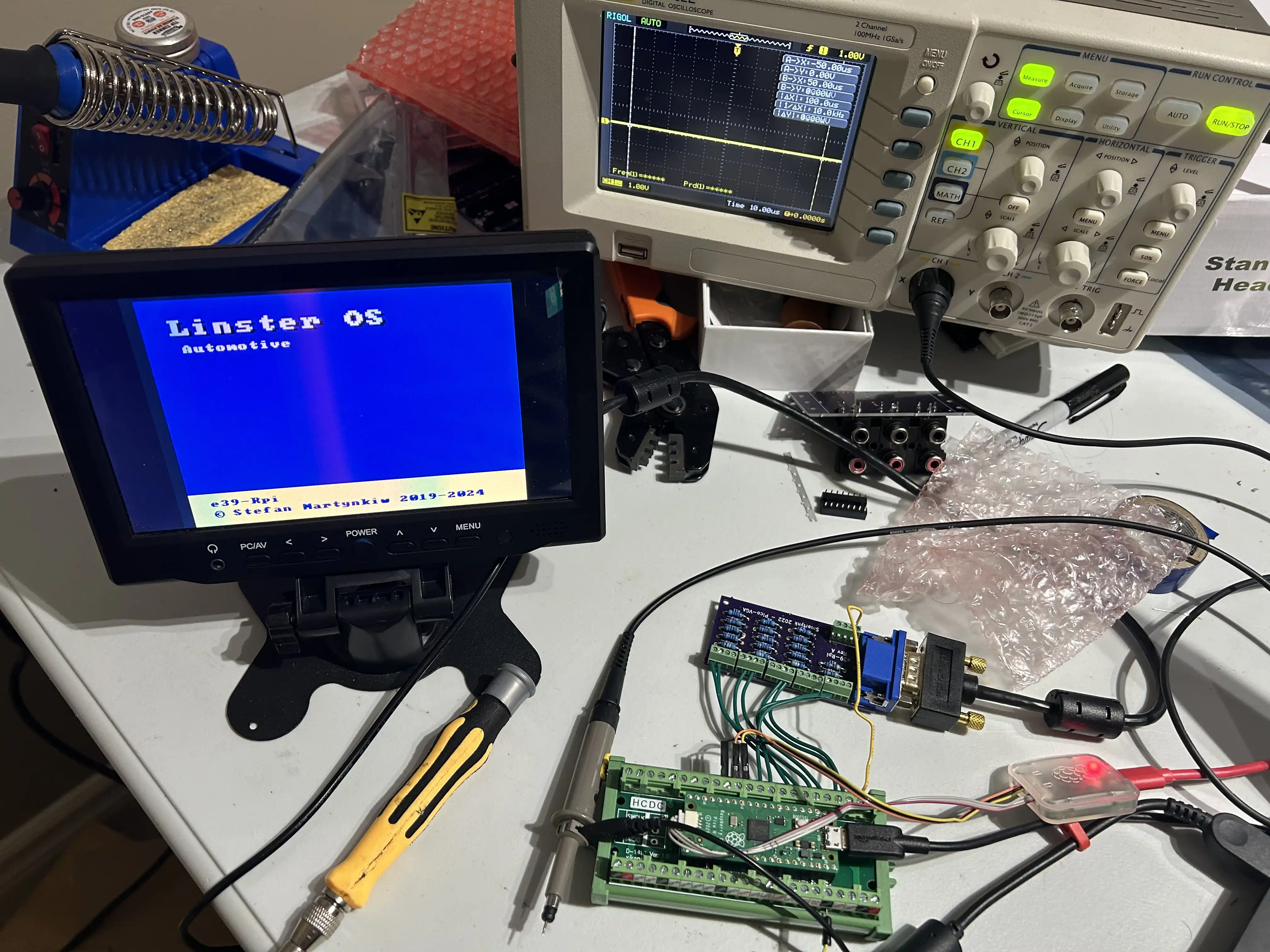
Hardware
First I tested the Pico graphics output with a RGB555 resistor ladder attached to a plain-old VGA monitor.
Then I tested the output with an equivalent RGB222 resistor ladder.
The resistor ladder board is a copy of the one that’s on the sled. I wired it up to the Pico manually.

VGA Timing
After verifying that the vga output worked, and that the graphics library was feature complete, the next challenge was to display it on the BMBT screen.
Overclocking
DMA failures because pixel clock not integer multiple of system clock.
Return to Top